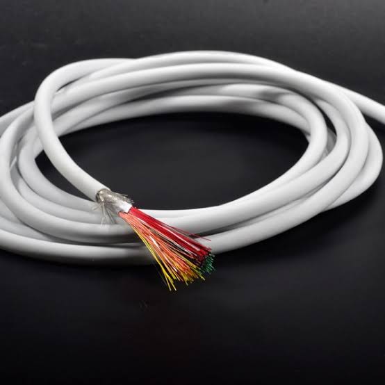
Ultrasound Probe Cable Assembly, Multi-Coax Build
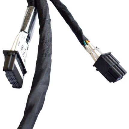
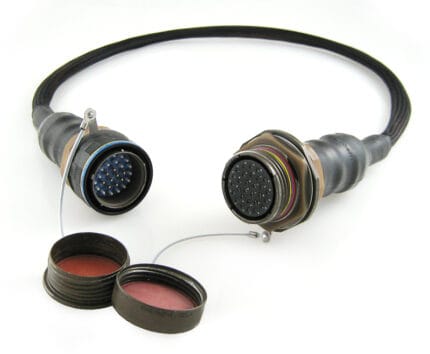
An ultrasound probe cable built to your transducer drawing: multi-micro-coax bundle, low-noise construction, overmolded at both ends. The cable and terminations, not the transducer.
Last updated: 13 September 2026
Overview
An ultrasound probe cable is a bundle of very small coaxial cores that has to stay electrically quiet while it is being coiled, dragged across a floor, run over by a cart and wiped down between patients. Every one of those events changes something the system can see. Micro-coax is geometrically fussy: if the dielectric shifts or the shield opens even slightly, the channel does not fail loudly, it just gets noisier, and a slightly noisier image is a clinical problem long before it is an electrical one. We build the bundle, the jacket and the terminations to your transducer drawing, and we are explicit that the transducer stack itself is your scope.
Scope of supply. We manufacture the cable assembly – the micro-coax bundle, screening, jacket, strain relief and terminations – built to your drawing. We do not manufacture the transducer or any finished imaging device, and we make no claim that this cable is an approved medical device. Performance of the finished system and its regulatory compliance remain your responsibility. Tell us what your registration requires of the cable part and we build and document to that.
Key Specifications
| Bundle | Multi-micro-coax cores per your drawing |
|---|---|
| Construction | Individually screened cores, constant geometry through the bend |
| Jacket | TPU or medical-grade PVC |
| Terminations | Probe end and system end per your drawing |
| Strain relief | Overmolded boots at both ends |
| Shield coverage | Braid and foil coverage stated per your drawing |
| Documentation | Material certificates and FAI in your format |
| Scope | Cable assembly only; transducer stack is your scope |
What kills this cable
| Stress | Failure mode | Design response |
|---|---|---|
| Bending fatigue at the probe end | Center conductor work-hardens and breaks; the channel drops out intermittently before it dies | Strand selection for fatigue, bend relief geometry cut to your shell |
| Cart wheels and door thresholds | Crush damage flattens the coax, changing impedance at that point | Crush-resistant jacket, and a protective sleeve where the run leaves the cart |
| Shield opening under repeated flexing | Gradual loss of noise performance rather than a hard fault | Braid angle and coverage set for flexing duty, not just for a static spec sheet |
| Fluid ingress at the probe joint | Corrosion and leakage paths at the termination | Sealed joint design, potting where specified, air-leak screening on the line |
| Tight coiling for storage | Permanent set in the bundle, cores migrate | Lay-up that recovers, plus a stated minimum coil diameter on the build sheet |
Why capacitance and geometry matter here
Each core in the bundle is a coaxial transmission line, and its behavior is set by the physical relationship between the center conductor, the dielectric and the shield. Change any one of those three and the line changes. That is the whole reason this cable is expensive and the whole reason it is delicate: the geometry that gives you a quiet channel is the geometry that gets disturbed when the cable is crushed.
What this means in practice is that the build has to hold that geometry through the two places where cables always get abused – the strain relief and the coil. Cores are laid to your channel map and kept at constant geometry through the bend relief rather than being allowed to bunch, and the bundle is laid so that repeated flexing does not let the cores migrate against each other.
Shield coverage and screening strategy
- Individual screen per core – the default for imaging bundles, because it stops channel-to-channel coupling. Costs more and adds diameter.
- Braid plus foil – foil gives coverage, braid gives the mechanical path for the drain and survives flexing better than foil alone.
- Coverage percentage – higher coverage means better screening and a stiffer, more expensive cable. We build to the coverage your drawing states and record it on the first-article report.
- Drain termination – terminated all the way around wherever the design allows it. A gathered drain is an inductor, and at imaging frequencies an inductor is not a connection.
Design notes from the build
Micro-coax terminations are soldered and potted per your drawing, and the potting is what stops a good termination from becoming a fatigue failure – it takes the load off the solder joint. The overmold geometry is cut on our own tooling, so when a boot does not sit right on your shell the mold is corrected in house rather than sent out. Where the drawing specifies a sealed joint, units are screened by air leak on the line.
One practical point worth raising early: tell us the channel count and the channel map at RFQ stage. A 64-channel bundle and a 192-channel bundle are not the same cable at different lengths, and the bend relief design changes with the bundle diameter.
Typical applications for this ultrasound probe cable
- General imaging and abdominal probes
- Endocavity and intraoperative probes with tight bend requirements
- Vascular and point-of-care handheld probes
- Veterinary imaging systems using the same platform
- Industrial non-destructive testing probes built on similar micro-coax bundles
- Imaging carts and system-side drops, alongside our Surgical Robot Cable Harness with Overmolded Strain Relief and Sealed Joints
How to specify your build
- Channel count and channel map.
- Core construction – micro-coax size, dielectric and screen, per your drawing.
- Probe end geometry and the termination method you use.
- System end connector and pinout.
- Jacket – TPU or medical-grade PVC, and the cleaning agents it sees.
- Length, minimum coil diameter, and the flexing duty.
- Documentation – material certificates, first-article report, inspection format.
Workmanship and testing
Assembly and inspection follow IPC-WHMA-A-620 Class 3 workmanship criteria under our ISO 9001 quality management system, with your acceptance criteria applied wherever your drawing is more specific than the standard. Every unit passes 100% continuity and pinout testing; screen continuity is checked on screened builds in the same pass, and sealed builds are air-leak screened. Electrical performance figures are the ones stated on your drawing – that is what we build and verify to, and we do not publish values of our own.
Custom builds and ordering
Prototypes start from 5 pcs and ship in 3 working days; production orders start at MOQ 500 pcs and ship 14 working days after approval. We hold 100 sets of mold tooling in house, so new overmold geometry adds about 10 working days. Our Longgang, Shenzhen plant runs four assembly lines with 40 assembly workers and 1,000,000 pcs annual output. Factory audits and video line tours can be arranged.
Related medical and micro-coax assemblies
- Surgical Handpiece Cable with Silicone Jacket
- Surgical Robot Cable Harness with Overmolded Strain Relief and Sealed Joints
- Patient Monitor ECG Lead Set, 5-Lead AHA
- Medical Panel Feedthrough Set for Cart and Monitor Enclosures
- 12G-SDI Coax Cable Assembly, BNC to BNC
- SMA to BNC RF Coax Patch Cable, 50 Ohm RG-58
Full range: custom wire harnesses.
Frequently Asked Questions
Do you build the transducer?
No. We build the cable assembly to your drawing. The transducer stack and the finished imaging system are your scope, and the compliance of the finished device sits with you as its manufacturer.
Can you repair or re-terminate an existing probe cable?
Sometimes, and it depends entirely on where the damage is. Send photographs and the channel count; if the bundle is intact and the damage is at the termination, a re-termination is often viable. If the cores are crushed mid-run, it usually is not.
What shield coverage do you use?
Whatever your drawing states. Coverage trades against flexibility and diameter, so it is your design decision, and we record what we built on the first-article report.
Why does the cable get noisier before it fails?
Because the failure is mechanical and progressive. Strands break one at a time and the shield opens gradually, so the channel degrades rather than dropping out – until the day it drops out.
What is the minimum order?
Minimum for a prototype run is 5 pcs, out the door in 3 working days. Volume production starts at 500 pcs and ships 14 working days after you approve the sample.
| Bundle | Multi-micro-coax cores per your drawing |
|---|---|
| Construction | Individually screened cores, constant geometry through the bend |
| Jacket | TPU or medical-grade PVC |
| Terminations | Probe end and system end per your drawing |
| Strain relief | Overmolded boots at both ends |
| Documentation | Material certificates and FAI in your format |
| Shield coverage | Braid and foil coverage stated per your drawing |
| Scope | Cable assembly only; transducer stack is your scope |