EV High Voltage Harness Built to Print for 800 V Battery Packs
An EV high voltage harness built to print for 800 V packs, junction boxes, charge inlets and the interlock loop. Conductor size, insulation and screen termination come from your drawing, and every leg is labeled at both ends. Send a drawing or a sample.
Last updated: 13 September 2026
Overview
An 800 volt traction pack is not a 400 volt pack with a different label on it. Moving the system voltage up changes what the insulation has to withstand, how the screen has to be terminated, and how much attention the distance between a live part and the vehicle structure deserves. An EV high voltage harness built for that has to treat insulation coordination, screen termination and the interlock loop as one design problem rather than three separate ones. We build each path, meaning pack internal, pack to junction box, inlet to contactor and the interlock loop, as its own assembly so that one damaged leg can be replaced without re-looming the vehicle.
Key Specifications
| Build Type | Build to print or build to sample |
|---|---|
| Conductor Size | Per your drawing; 32 to 12 AWG standard, larger power cores to order |
| Insulation | XLPE or silicone, temperature class per your drawing |
| Voltage Class | 800 V class system, or otherwise as stated on your drawing |
| Current | Per leg, as stated on your specification |
| Screening | Foil and braid with the drain termination defined on the drawing |
| Interlock | HVIL loop routed as a separate circuit |
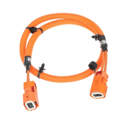
| Identification | Orange high voltage jacket, labels at both ends |
| Workmanship | IPC/WHMA-A-620 criteria, class per drawing |
| Testing | Continuity, dielectric withstand, crimp pull test |
Insulation coordination: what we control
The insulation requirement for a traction system comes out of the coordination study your engineering team performs for the vehicle: working voltage, overvoltage category, pollution degree, and the clearance and creepage distances that follow from them. Those figures belong to your design and go on the drawing. What we control is everything a harness builder can get wrong. In an electric vehicle pack the usual offenders are a strip length that leaves too much bare conductor at a terminal, a crimp that lets strands escape toward a neighboring pole, a marker sleeve placed where it bridges two points, and a bend radius tight enough to push a live terminal against the enclosure. Each of those is checked on the drawing and on the part.
Ask three suppliers how to end a screen and you will get four answers. These are the options, with the trade-off stated plainly:
| Method | What it gives you | What it costs | When we would use it |
|---|---|---|---|
| 360 degree termination to the connector shell | The screen continues through the interface with no break | Needs a connector and backshell designed for it | The default for high current legs running beside low voltage looms |
| Foil plus braid with a short drain | Good coverage and a simple build | The drain becomes the weak point if it is left long | Where the connector does not support a full circumferential interface |
| Screen bonded at one end only | Avoids a ground loop between two boxes | Needs the decision stated on the drawing, not left to the line | Where your electromagnetic compatibility plan calls for it explicitly |
| Overall screen over the whole loom | One treatment for a mixed loom | Can hide a leg that needed its own screen | Where the drawing accepts a single treatment |
The third row is the one that needs a decision rather than a default. Whether a screen is bonded at one end or both is an electromagnetic compatibility choice that belongs to the vehicle, not to the harness.
The interlock loop
The high voltage interlock loop tells the vehicle that a service plug has been removed or a cover has been opened, and it only does that job while it is independent. We route it as its own circuit with its own connector positions rather than splicing it into a power leg, and we make sure it opens first and closes last in the mating sequence so the controller sees the break before anything else can happen. Series or parallel is your call and goes on the drawing.
Identification and workmanship
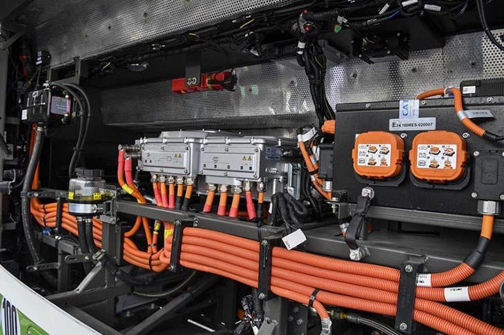
Orange outer jacket is the conventional high voltage identification in traction battery practice, and every leg is labeled at both ends. The loom is built to IPC/WHMA-A-620 workmanship criteria with the class specified on your drawing. We do not hold ourselves out as holding a certification your program has not audited: we build to the criteria you name and document what we did, including crimp tooling settings and pull test results, so your process file has evidence rather than an assertion.
Typical applications for this EV high voltage harness
- Module to module and module to junction box links inside the pack
- Pack to high voltage junction box, and pack to onboard charger runs
- Charge inlet to contactor assemblies
- Interlock loop looms built as their own part number
- Prototype and pre-production looms built to the same drawing as production
Testing
- Continuity and polarity on every power and interlock circuit
- Dielectric withstand test at the voltage stated on the drawing
- Crimp pull test on first-piece and sampled production parts
- Screen continuity and insulation resistance recorded per serial number
Custom builds and ordering
Each assembly is built and inspected to IPC/WHMA-A-620 Class 3 criteria within an ISO 9001 quality system, covering 32 to 12 AWG. Continuity and pinout are tested on every unit before packing. Where the specification calls for an ingress rating, seal checking on the batch can be quoted.
Five pieces is where a prototype starts and it ships in 3 working days. Production requires 500 pcs minimum and takes 14 working days after approval. Non-stock tooling adds around 10 working days. Private-label builds ship under your part number and labeling; material certificates and first-article reports are available on request.
Frequently Asked Questions
Do you build the interlock loop into the power harness?
We can, but we advise against it. Routing it as a separate circuit with its own connector positions keeps it independent of the condition of the power conductors.
How do you terminate the screen?
To the method on your drawing. Where the connector supports it we use a 360 degree interface; where it does not, we use a short drain and record the length on the build record.
Can you build from a sample from an earlier build stage?
Yes, and it is often the fastest route to an accurate quote. Send the sample with the connector part numbers and the current per leg.
What is the prototype quantity?
For prototypes the floor is 5 pcs and lead time is 3 working days. Production orders begin at 500 pcs and ship 14 working days after sample sign-off.
Related assemblies
- BESS Battery Wiring Harness Built to Drawing for 1000-1500 V DC Storage Racks
- Hydrogen Electrolyzer Cable Harness with HVIL for High-Temperature Stacks
- BMS Communication Harness for CAN and RS-485 Battery Rack Links
- 38999 High Speed Harness with Overmolded Strain Relief for 10GbE Links
- M12 K-Coded Power Cable for 630 V AC Motor Feeds
- M12 S-Coded Power Cable for Single-Phase AC Loads
Full range: Custom Wire Harnesses.
| Build Type | Build to print or build to sample |
|---|---|
| Conductor Size | Per your drawing; 32 to 12 AWG standard, larger power cores to order |
| Insulation | XLPE or silicone, temperature class per your drawing |
| Voltage Class | 800 V class system, or otherwise as stated on your drawing |
| Current | Per leg, as stated on your specification |
| Screening | Foil and braid with the drain termination defined on the drawing |
| Interlock | HVIL loop routed as a separate circuit |
| Identification | Orange high voltage jacket, labels at both ends |
| Workmanship | IPC/WHMA-A-620 criteria, class per drawing |
| Testing | Continuity, dielectric withstand, crimp pull test |