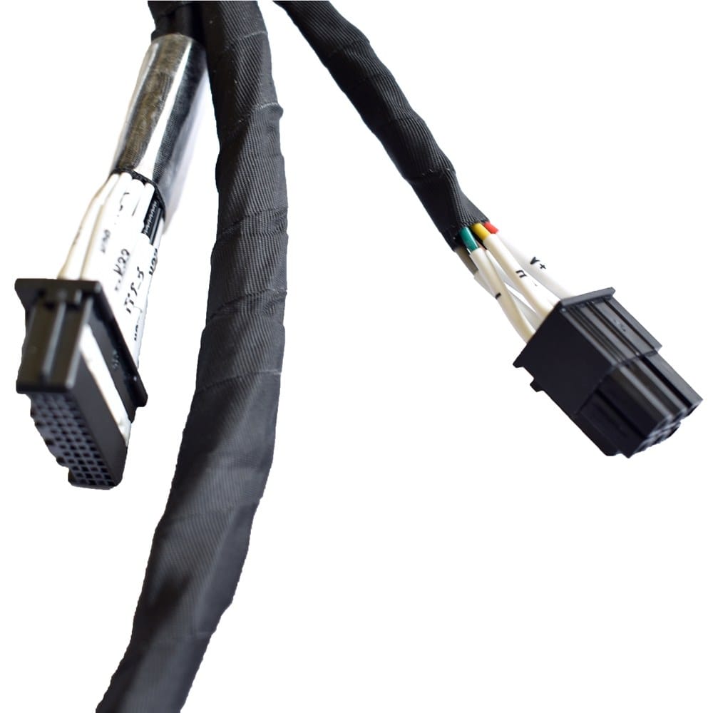
BMS Communication Harness for CAN and RS-485 Battery Rack Links
A BMS communication harness for CAN and RS-485 battery racks, built as screened twisted pairs with keyed and latched housings, numbered legs and a defined screen termination. Sense wiring is kept out of the power path. Send the pinout and the node list.
Last updated: 13 September 2026
Overview
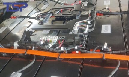
A battery rack runs two wiring jobs at once and they want opposite things. The power legs move current and do not care about noise; the supervision layer moves millivolt sense readings and diagnostic traffic and cares about almost nothing else. A BMS communication harness covers the second job: cell voltage and temperature sense leads, the CAN link between the battery management unit and the power conversion system, cabinet level RS-485, and the sensor wiring for thermal management. Designing it starts from the topology of the bus, not from a cable catalog.
Key Specifications
| Build Type | Build to drawing or build to sample |
|---|---|
| Conductor | 26 to 22 AWG screened twisted pairs |
| Protocols | CAN, RS-485 and daisy chain sense leads |
| Screening | Foil or braid screen with drain termination specified on the drawing |
| Identification | Color coding plus printed markers per node |
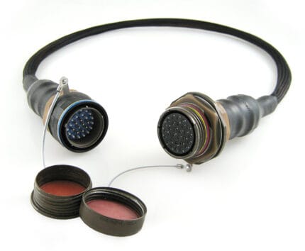
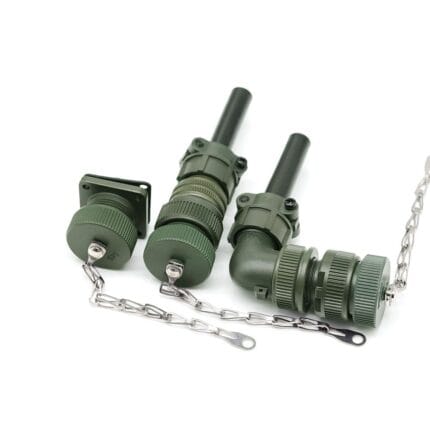
| Connector Style | Keyed and latched housings to prevent mis-mating |
| Sealing | Optional potted or overmolded transitions for outdoor enclosures |
| Testing | 100% continuity, dielectric withstand, screen continuity |
The wiring follows the bus, so the first question is always which shape the network has. On a CAN bus or an RS-485 segment the harness is part of the physical layer, and it can break the bus in ways no software diagnostic will explain:
| Topology | What the loom has to support | Typical fault when it is ignored |
|---|---|---|
| Daisy chain between modules | One leg per node, with the order fixed by the rack layout | Two legs swapped at build and a rack that reports cells in the wrong order |
| CAN bus trunk with drops | A defined trunk and defined drop lengths | Long unterminated stubs that reflect once the bus is running at speed |
| RS-485 multi-drop | One pair continuing through every node, with a defined end | A star branch added during installation because it was convenient |
| Point to point sense leads | One pair per measurement point, kept away from power | Sense leads bundled with a feeder and picking up switching noise |
| Mixed in one loom | All of the above, with the boundaries marked on the drawing | A single treatment applied to all of them |
The middle column is what we need on your drawing. Without it the loom gets built as a generic cable set and the diagnostics team is left to work out why.
Termination resistors: where they belong
Whether a bus needs a terminating resistor, of what value and how many, is decided by your bus design and stated on your drawing. We do not fit one because it looked right on a previous build. What we will do is tell you where in the loom the terminator physically belongs, which on a rack is usually at the two extreme nodes and often not where the harness naturally ends, and build the branch or the connector position that puts it there. If you want them inside the connector rather than in the loom, say so; both are buildable and they service very differently.
Noise behavior
Screen effectiveness depends on the termination at least as much as on the cable. Where a rack sits next to a switching power stage, we agree the screen termination method with you in advance, keep drain lengths short, and separate sense wiring from power runs in the loom layout. Where an attenuation or noise figure appears on a competitor data sheet, we treat it as a target to be verified on the finished assembly rather than as a result we can promise. If the environment is genuinely difficult, the fix is usually physical separation in the routing before it is a better cable.
Keying per rack slot
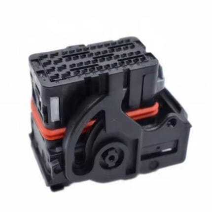
Adjacent rack slots are the easiest thing in the world to mis-mate, and a sense lead plugged one slot over reports believable nonsense rather than an open circuit, which is far worse during commissioning. We use keyed and latched housings, key them differently per slot where the drawing calls for it, and print the node number on both ends of every leg so fault finding does not depend on a pinout printout that has walked off site.
Typical applications for this BMS communication harness
- Cell voltage and temperature sense leads inside a rack
- CAN links between the battery management unit and the power conversion system
- Cabinet level RS-485 between racks in a container
- Thermal management and fire detection sensor wiring
- Retrofit harnesses for installed racks, built from a sample
Testing and records
- Continuity check on every conductor, 100% of harnesses
- Dielectric withstand test at the voltage stated on the drawing
- Screen continuity and drain termination inspection
- Serialized test records supplied with the shipment
Workmanship and ordering
ISO 9001 governs the line and IPC/WHMA-A-620 Class 3 governs the workmanship. Terminations cover 32 to 12 AWG. No unit is packed before continuity and pinout have been verified, and where an ingress rating is specified we can quote seal checking on the production batch.
From 5 pcs for a prototype, shipped in 3 working days, to 500 pcs and up for production at 14 working days after approval. Tooling we already hold costs no lead time; a new body adds roughly 10 working days. Private-label shipments carry your part number and labeling, and we can supply material certificates plus a first-article report.
Frequently Asked Questions
Do you fit the terminating resistors?
Only where your drawing specifies them, with the value and the position stated. We will point out where they physically belong on a daisy chain and build the connector position or branch for them.
Can each rack slot be keyed differently?
Yes. Keyed and latched housings can be keyed per slot so a leg cannot be plugged into the wrong node, and we print the node number on both ends as well.
Can the harness be sealed for an outdoor enclosure?
Yes. We pot or overmold the connector transitions and use sealed housings. Tell us the installation environment and we will propose an approach for your review.
What is the prototype quantity?
Sample quantity starts at 5 pcs with 3 working days to ship. Once the sample is approved, production from 500 pcs takes 14 working days.
Related assemblies
- BESS Battery Wiring Harness Built to Drawing for 1000-1500 V DC Storage Racks
- Energy Storage Cabinet Wiring Harness
- Leak Detection Harness for Data Center CDU and Rack Manifolds
- EV High Voltage Harness Built to Print for 800 V Battery Packs
- M12 CAN Bus Cable, 5-Pin Shielded Pair for CANopen and DeviceNet
- M12 12 Pin Cable, High Density Cordset for Encoders and Valve Blocks
Full range: Custom Wire Harnesses.
| Build Type | Build to drawing or build to sample |
|---|---|
| Conductor | 26 to 22 AWG screened twisted pairs |
| Protocols | CAN, RS-485 and daisy chain sense leads |
| Screening | Foil or braid screen with drain termination specified on the drawing |
| Identification | Color coding plus printed markers per node |
| Connector Style | Keyed and latched housings to prevent mis-mating |
| Sealing | Optional potted or overmolded transitions for outdoor enclosures |
| Testing | 100% continuity, dielectric withstand, screen continuity |