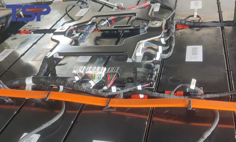
BESS Battery Wiring Harness Built to Drawing for 1000-1500 V DC Storage Racks
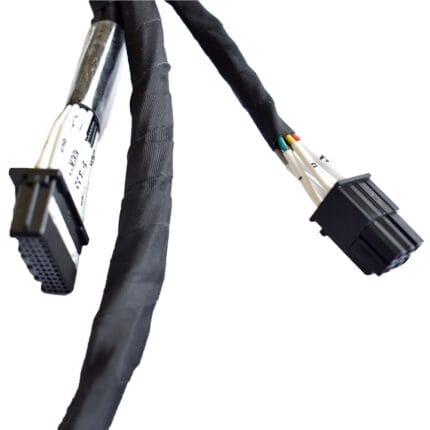
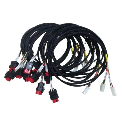
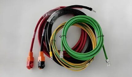
A BESS battery wiring harness built to drawing for storage cabinet racks, from module links through to the power conversion skid. Conductor, insulation, screen and terminations are selected to your specification, and every leg is marked to your node numbering.
Last updated: 13 September 2026
Overview
A BESS battery wiring harness is a short link doing a hard job. Inside a storage cabinet the run from a module terminal to a busbar or a junction box is often under a meter, but it carries continuous current in a hot enclosure, it is bent into a tight radius during installation, and it sits next to the sensing wiring that decides whether the rack keeps running or trips. Rack layouts differ on terminal geometry, bend radius and the spacing your design requires between live parts, so these are never stocked items. We cut, crimp, mark and test each assembly against your drawing, your sample or a pinout table with node numbers.
Key Specifications
| Build Type | Build to drawing or build to sample |
|---|---|
| Conductor Range | 32 to 12 AWG standard; larger power cores per your drawing |
| Conductor Material | Tinned or annealed copper, fine strand for tight routing |
| Insulation | XLPE or XLPO, class stated per your drawing |
| Jacket Options | UV resistant, oil resistant, flame retardant per specification |
| Screening | Optional foil plus braid with drain termination defined on the drawing |
| Typical Length | 0.3 m to 1.5 m, or per your layout drawing |
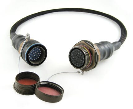
| Terminations | TE Connectivity, Amphenol, Staubli style or customer specified |
| Identification | Heat-shrink or clip-on markers per node numbering |
What a cabinet does to a loom
Three things separate a cabinet loom from a machine loom. The first is heat without airflow: a sealed enclosure late in a charge cycle is a very different environment from an open frame. The second is sustained direct current, which is less forgiving of a marginal termination than alternating current because there is no current zero to break an arc. The third is access. A module link is usually installed once, by hand, in a crowded rack, and any loom that needs two people and a lever to fit will be damaged during installation. That last point decides more about the routing than the electrical design does.
Clearance and creepage: what we control
The spacing between live parts, and across the surface of the insulation between them, is set by your system design rather than by the cable supplier. In grid-scale storage the practice is normally taken from the insulation coordination your engineering team performs for the installation, and the figures that come out of that study are the ones we build and verify to. What we control on our side is everything a harness can get wrong: the length of stripped conductor at a terminal, the distance from the crimp barrel to the end of the insulation, the position of a marker sleeve that could bridge two points, and the bend radius that pushes a live terminal toward its neighbor. Those go on the drawing and we check them. Daily thermal cycling also means a termination that is correct cold and marginal hot is not acceptable.
Selection starts from the environment rather than from a catalog:
| Element | Options we build with | How to choose |
|---|---|---|
| Conductor | Tinned or annealed copper in fine strand | Fine strand for tight routing and repeated handling; tinned where the terminal environment calls for it |
| Insulation | XLPE or XLPO | Selected for continuous duty inside a hot enclosure, class per your drawing |
| Outer jacket | UV resistant, oil resistant, flame retardant | Choose by exposure: outdoor container, cabinet interior, or a skid with hydraulic equipment close by |
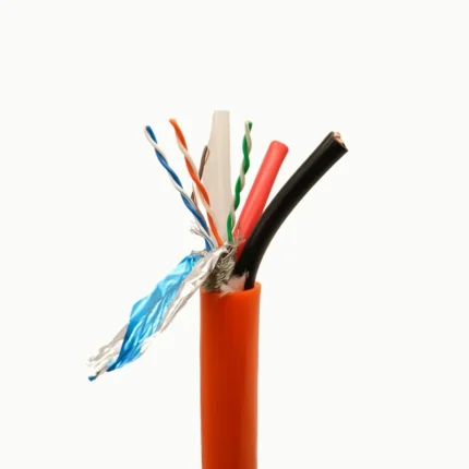
| Screen | Foil plus braid with defined drain, or unshielded | Where the power conversion stage couples switching noise into adjacent signal wiring |
| Protection | Abrasion sleeving at rub points and panel pass-throughs | Anywhere the loom touches a frame edge or is pulled through a cut-out |
If your specification names a compound, name it on the drawing and we source to it. If it does not, we propose one and you approve it before the build starts.
Power and supervision wiring do not belong in the same bundle. These are the four ways we keep them apart, in descending order of preference:
| Separation method | When it is used | What it costs |
|---|---|---|
| Physically separate assemblies | Power links and sense harnesses bought under different part numbers | Two part numbers to manage, but the cleanest result |
| Separate branches in one loom | Where part of the route has to be shared | Needs the branch point defined on the drawing |
| Screened sense legs | Where sharing the route is unavoidable | Screen termination has to be specified, not assumed |
| Spacing held in the routing | Across terminals and busbar areas | More care during installation; worth it at a module terminal |
The last row is the one that gets skipped. A sense lead dressed against a power terminal because it was convenient is a fault that only shows up under load.
Terminations
We terminate the connector families already on your bill of materials and can source TE Connectivity, Amphenol and Staubli style parts, or build with a brand you nominate. If you only have a photograph of the mating face, send it and we will identify the series before quoting. Crimp tooling is set per terminal and verified by pull test on the first piece, not by eye.
Typical applications for this BESS battery wiring harness
- Module to module and module to busbar links inside a rack
- Rack to junction box, and rack to power conversion skid runs
- Container and cabinet level distribution looms
- Auxiliary power and thermal management wiring inside the enclosure
- Replacement links for installed cabinets, reproduced from a sample
Testing before shipment
- Continuity and polarity verification on every circuit, 100% of units
- Dielectric withstand test at the voltage stated on the drawing
- Crimp pull test on first-piece parts and on sampled production units
- Insulation resistance recorded against the harness serial number
Workmanship and ordering
The line works to IPC/WHMA-A-620 Class 3 under ISO 9001, terminating 32 to 12 AWG. Every unit gets a continuity and pinout test before it is packed. Seal checking on the production batch is available when an ingress rating is in the specification.
Prototype quantity starts at 5 pcs with a 3 working day turnaround, and production starts at MOQ 500 pcs shipping 14 working days after approval. Where a new tool is needed, allow about 10 working days. We ship OEM and ODM builds under your part number and labeling, and can provide material certificates and first-article reports.
Frequently Asked Questions
Can you build from a sample link?
Yes, and it is usually the fastest route. Send the removed link, or a photograph with the overall length and the terminal part numbers.
Do you supply the terminals and connectors?
We can, by sourcing the families on your bill of materials, or we build with free-issued parts. Say which on the enquiry.
How short can a module link be?
Short enough that the bend radius becomes the constraint rather than the length. Give us the terminal geometry and we will tell you what is buildable.
Do you mark each leg?
Yes. Heat-shrink or clip-on markers matched to your node numbering, on every leg and at both ends where the drawing asks for it.
Related assemblies
- Energy Storage Cabinet Wiring Harness
- BMS Communication Harness for CAN and RS-485 Battery Rack Links
- EV High Voltage Harness Built to Print for 800 V Battery Packs
- Hydrogen Electrolyzer Cable Harness with HVIL for High-Temperature Stacks
- M12 S-Coded Power Cable for Single-Phase AC Loads
- M12 K-Coded Power Cable for 630 V AC Motor Feeds
Full range: Custom Wire Harnesses.
| Build Type | Build to drawing or build to sample |
|---|---|
| Conductor Material | Tinned or annealed copper, fine strand for tight routing |
| Insulation | XLPE or XLPO, class stated per your drawing |
| Jacket Options | UV resistant, oil resistant, flame retardant per specification |
| Screening | Optional foil plus braid with drain termination defined on the drawing |
| Typical Length | 0.3 m to 1.5 m, or per your layout drawing |
| Terminations | TE Connectivity, Amphenol, Staubli style or customer specified |
| Identification | Heat-shrink or clip-on markers per node numbering |
| Conductor Range | 32 to 12 AWG standard; larger power cores per your drawing |