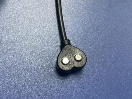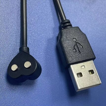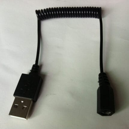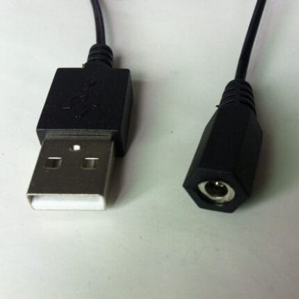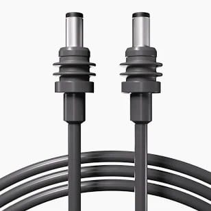
Starlink Mini DC Extension Cable – DC 5.5×2.1mm Male to Male, 18 AWG
A starlink mini dc extension cable that adds reach between the supply and the dish without changing the voltage it sees: molded 5.5×2.1mm male plug to female jack, 18 AWG stranded tinned copper, 1 m or 3 m, and custom lengths to your drawing.
Overview
A Starlink Mini DC extension cable adds reach between the supply and the dish
without changing the voltage the dish sees. The lead that ships with the terminal is sized for a
desk, not for a roof rack, a mast or a dash, and in practice it is the cable that decides where the
dish can be mounted. This build is a molded 5.5 x 2.1 mm male plug on one end and a molded 5.5 x 2.1 mm
female jack on the other, with 18 AWG stranded tinned copper between them. It goes in line with the
lead you already have, so nothing else about the installation changes.
Key Specifications
| Cable type | DC power extension cable |
|---|---|
| Connector A | DC barrel 5.5 x 2.1 mm male, molded |
| Connector B | DC barrel 5.5 x 2.1 mm female, molded |
| Conductor | 18 AWG stranded tinned copper |
| Voltage range | 12 / 24 V DC |
| Jacket | PVC, -40 to +80 ℃ |
| Length | 1 m / 3 m, custom on request |
| Polarity | Center positive, pass-through, no reversal |
Which terminal this fits
Match the cable to the terminal in front of you, not to the box art. This build is for the compact
terminal that takes a round 5.5 x 2.1 mm barrel input. It does not suit the larger Generation 2 and
Generation 3 units or the Flat High Performance panel of the Starlink family, which use different power arrangements. The fastest
check is the output plug on the supply you already own: if it is a 5.5 x 2.1 mm barrel with center
positive polarity, this extension continues it. If it is anything else, send us a photo of the label
and the plug before ordering.
We build compatible DC leads for these installations and are not affiliated with the terminal
manufacturer. Trademarks belong to their owners.
Identifying the lead you have now
- Read the supply label. Output voltage and current are printed on it, and that
tells you what the run has to carry. - Measure the plug. A caliper across the barrel gives the outside diameter; a plug
that rattles in the socket is the wrong size even if it looks right. - Check the polarity. Most of this gear is center positive, and the symbol is
molded or printed on the supply. A meter on the barrel confirms it in seconds. - Count the joints. Every inline connection is one more place for voltage to be
lost and for water to get in.
Why the original lead is the weak point
OEM leads are built to a price and a packing size, and three things follow from that. They are
short, so the dish ends up where the cable allows rather than where the sky view is best. The barrel
joint is a friction fit with no collar, so vibration on a roof rack or a mast works it loose over a
season. And the jacket is usually a general-purpose PVC that stiffens in cold weather and goes brittle
after a couple of summers of sun. An extension does not fix all three, but a molded body with a sealing
collar at each end removes the joint that fails first, and a UV-stable jacket removes the second.
Choosing a length: what voltage drop costs you
On a 12 V run the limiting factor is usually drop, not the current rating of the wire. The numbers
below are nominal resistance values for stranded copper at 20 ℃, given for estimating only.
Both conductors in the pair count, so a 3 m cable is 6 m of copper in series.
| Conductor | Nominal resistance per meter | Round-trip at 3 m | When we quote it |
|---|---|---|---|
| 18 AWG | About 21 mΩ | About 126 mΩ | Stock build, 1 m and 3 m |
| 16 AWG | About 13 mΩ | About 78 mΩ | Longer runs at higher current |
| 14 AWG | About 8.3 mΩ | About 50 mΩ | Long cabin or mast runs |
Multiply the round-trip figure by your load current to get the drop in volts, then check it against
the input range on the terminal label. The drop your assembly is built and verified to is the figure
stated on your drawing; send us the one-way distance and the load current and we size the conductor
before you commit to a build.
Typical applications for this Starlink Mini DC extension cable
- Van, RV and truck roof mounts where the indoor unit sits further forward than the OEM lead reaches
- Boat installations where the run has to clear a cabin, a bulkhead and an engine bay
- Mast and pole mounts at events, film sets and temporary sites that need the dish away from foot traffic
- Backup and emergency comms kits packed with a Starlink Mini car charger cable for vehicle power
- Fixed installs fed from a fused DC panel, alongside our 14 AWG DC barrel pigtail cable
Routing and installation notes
- Leave a drip loop below every inline joint so water does not track along the jacket into the coupler.
- Support the cable every 300 to 500 mm on a vibrating mount; a barrel joint carrying the weight of a hanging loop will work loose.
- Where the run passes through a panel or a bulkhead, use a grommet. A sharp edge plus vibration cuts a jacket in a season.
- Do not coil the surplus tightly. A tight coil is an inductor and a heater, and it holds heat on a roof in summer.
- Keep the run away from antenna cables where possible, or cross them at right angles rather than running them parallel.
How to specify your build
- Length — measured as installed, not as the crow flies.
- Conductor size — or give us the load current and the distance and we size it.
- Jacket — standard PVC, or a UV and oil resistant compound for exterior and engine bay runs.
- End style — straight or right-angle barrel, and which end needs to be which.
- Print on the jacket and the label or part number you want on the bag.
- Quantity, and whether this is a sample or a production order.
Workmanship and testing
Starlink Mini DC Extension builds are made to IPC/WHMA-A-620 Class 3 workmanship inside an ISO 9001 system, over a 32 to 12 AWG range. No Starlink assembly is boxed before continuity and pinout are confirmed, and seal checking is quoted whenever an ingress rating is on the drawing.
RoHS and REACH declarations are provided per project together with the agreed test reports; the documentation scope is listed under certifications and compliance. If your drawing specifies a UL style, we build to that drawing and supply the UL reference with the shipment instead of substituting an equivalent. Where this build needs an overmold, the tool is designed, cut and maintained in our own shop under in-house mold making and overmold tooling, and it is never used for another customer’s program. Related reading: what outdoor duty does to a jacket.
Related DC power leads
- Starlink Mini Car Charger Cable, 12/24 V lighter plug to DC 5.5×2.1mm
- Mini UPS Splitter Cable DC 5.5×2.1mm
- IP67 Waterproof DC Extension Cable 5.5×2.1mm Male to Female
- IP67 DC to USB-C Cable, 5.5×2.1mm Barrel Power Lead
- 12V/24V Cigarette Lighter Power Cable with Waterproof DC Plug
Full range: DC Plug Power Cable.
Frequently Asked Questions
Will an extension change the voltage at the dish?
Any cable drops some voltage. At 18 AWG and the stock lengths the drop stays small for typical loads, but on a long run at high current it matters. Give us the length and the load current and we will size the conductor so the drop stays inside the terminal’s input range.
Can I join two extensions to get more reach?
You can, and we would rather you did not. Every joint adds resistance and a place for water to get in. One longer cable in a heavier gauge is the better answer.
Is the barrel center positive?
Yes, and the cable is pass-through, so it does not reverse polarity. Check the supply you are plugging into as well, because the extension can only pass through what it is given.
Do you make a right-angle version?
Yes. A right-angle barrel on one end is a common request where the dish sits close to a bulkhead or a wall.
What is the minimum order for a custom length?
For Starlink Mini DC Extension builds, prototypes run from 1 to 50 pcs with a 3 working day turnaround; volume orders begin at 500 pcs and ship 14 working days after sample approval.
| Cable type | DC power extension cable |
|---|---|
| Connector A | DC barrel 5.5 x 2.1 mm male, molded |
| Connector B | DC barrel 5.5 x 2.1 mm female, molded |
| Conductor | 18 AWG stranded tinned copper |
| Voltage range | 12 / 24 V DC |
| Jacket | PVC, -40 to +80 C |
| Length | 1 m / 3 m, custom on request |
| Polarity | Center positive (pass-through, no reversal) |
Related products
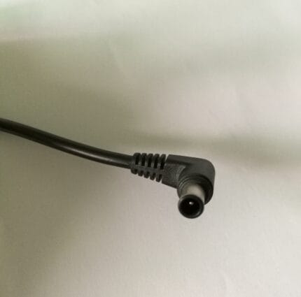
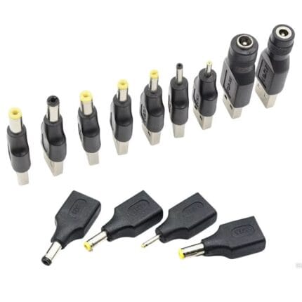
DC Barrel Adapter Kit – 5521 / 5525 / 4017 / 3513 / 1.35mm / 2.5mm, 6-Piece
A dc barrel adapter kit covering 5.5x2.1, 5.5x2.5, 4.0x1.7, 3.5x1.35 and 2.5 mm in six molded female-to-male adapters, so one supply covers a mixed estate. Center positive throughout, with nickel-plated brass contacts. Measure the socket pin with a caliper before ordering: the outer shell is identical across three of these five sizes. Bagged with a size card, or boxed with a printed insert.