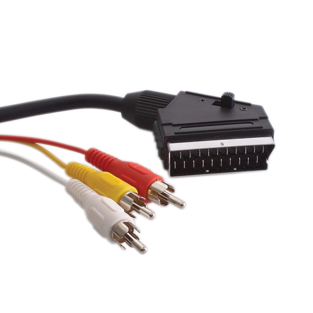
SCART to 3 RCA AV Cable
A scart rca av cable breaking a 21-pin SCART output into composite video plus stereo audio, for legacy European gear on a modern TV or capture card. Coaxial video core, locking clip, direction built to your source.
Overview
A scart rca av cable breaks the 21-pin SCART connector used across
Europe from the 1980s onward into the three plugs a modern television, capture card or digitizing
workflow still recognizes: yellow composite video, red and white analog audio. It exists because there
is a lot of legacy equipment still in service – set-top boxes, VCRs, DVD players, classic game
consoles – and almost nothing new to plug them into. The catch is that SCART was never one signal. It
was a carrier for several, and a passive breakout can only reach the one your source is actually
outputting at that moment.
Key Specifications
| Connector A | SCART (21-pin) male, with locking clip, integrated cable |
|---|---|
| Connector B | 3x RCA male (yellow composite video, red + white analog audio) |
| Cable Length | Custom on request (typical 1-2 m) |
| Jacket | Black PVC |
| Application | Legacy European AV equipment to a modern TV or capture card |
| Video carried | Composite video only, on a coaxial core |
| Audio carried | Analog left and right |
| Not carried | RGB, S-Video, or any digital signal |
| Body | Molded 21-pin shell with a locking clip |
| Build | Length, jacket and pinout per your drawing |
Why a scart rca av cable sometimes gives you no picture
The 21-pin shell carries composite video, RGB video with its own switching signal, stereo audio in
both directions, and a set of status and control lines. Which of those are live is decided by the
source, not by the cable. If the source is set to output RGB, it asserts a blanking voltage on one of
the control pins and puts the picture on the red, green and blue pins instead of on the composite
video pin. A passive cable has no way to convert that, so you get sound and a black screen, and the
cable gets blamed.
| Symptom | What it usually means | What to do |
|---|---|---|
| Sound, no picture | The source is set to RGB output | Switch the source menu to composite, or use an active RGB to composite converter |
| Picture, no sound | Audio is wired to the other pair of pins for the direction you are using | Confirm whether the device is a source or a display and order that direction |
| Black and white picture | A PAL source into an NTSC-only display, or the reverse | Check the standard on both ends; a capture card can usually be set to accept either |
| Nothing at all | The plug is not fully seated, or the socket is a display input rather than a source output | Seat the plug fully and check the direction |
| Sound and picture, but soft and noisy | Composite video over a long run, or a source with a poor encoder | Shorten the run; for archival work use an S-Video or RGB path if the source offers one |
Direction: the same 21 pins, wired two ways
Sources and displays use the same shell, but they do not use the same pins for the same job. A
device that shows pictures puts composite video out on one pin and takes it in on another; a device
that makes pictures does the opposite. That is how a straight-through SCART to SCART lead can connect
anything to anything. It is also why a breakout cable has to be built for the direction you need: one
that taps the output of a set-top box is not the same part as one that taps the output of a
television.
Tell us which way the signal is going when you order. If you are digitizing a VHS collection, the
source is the VCR. If you are sending a modern set-top box to an older capture device, the source is
the set-top box. Where one cable has to do both jobs, ask for a build with a direction switch; it costs
a little more and removes the guesswork. The
SCART interface is
old enough that several generations of equipment wired it differently, so the pinout on your drawing is
what we build and verify to.
Mechanical notes: seating, and the clip
Two mechanical details cause more field failures than any electrical issue. First, a 21-pin plug is
wide and shallow, and it has to go in straight and all the way; a plug that is 2 mm short gives you
intermittent audio or a rolling picture. The locking clip on the shell is there to hold it in, and it
should be engaged every time. Second, the pins inside a SCART socket bend, and a bent pin turns into a
short across two signals. Never force the plug, and check the socket before you conclude the cable is
faulty.
Typical applications for this scart rca av cable
- Older European set-top box or VCR into a modern TV with composite and stereo inputs
- Digitizing VHS and legacy tape with a capture card
- Classic game consoles into a capture device or a modern display
- DVD players and satellite receivers in holiday properties and second rooms
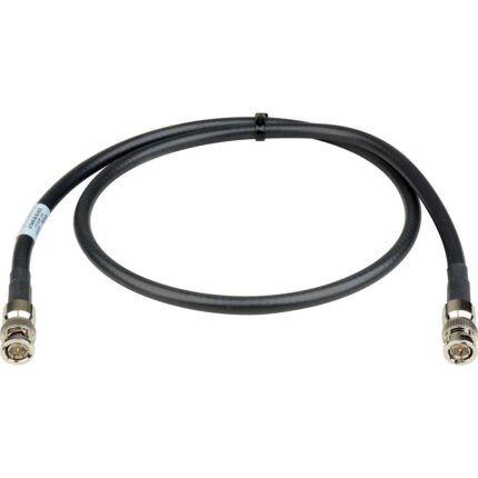
- Archival and museum work, racked alongside
75 ohm SDI runs for the newer
material in the same collection
How to specify your build
- Direction – source to display, or display output to a recorder.
- What the source outputs – composite, or RGB that needs an active converter.
- Length, typically 1 to 2 m; composite does not like long runs.
- Regional standard if you know it, so the build is tested on the right
equipment. - Quantity, and whether you need retail packing for resale.
For SCART builds the line runs to IPC/WHMA-A-620 Class 3 under ISO 9001, terminating 32 to 12 AWG. Every SCART build gets a continuity and pinout check before it is boxed, and seal checking is quoted whenever an ingress rating is on the drawing.
Custom builds and ordering
SCART prototype lots start from 1 to 50 pcs and ship in 3 working days; production requires 500 pcs and runs 14 working days after sample approval. Tooling not already held adds around 10 working days. Your part number and labeling go on OEM and ODM SCART shipments, and material certificates and first-article reports are available on request.
RoHS and REACH declarations are provided per project together with the agreed test reports; the documentation scope is listed under certifications and compliance. If your drawing specifies a UL style, we build to that drawing and supply the UL reference with the shipment instead of substituting an equivalent. Injection parameters for this part are developed against the jacket material using the approach documented under overmold materials and injection parameters. More background: what stage and studio work demands. Any tooling we cut for this part stays yours, maintained in our own tool room under your part reference.
Related video and audio assemblies
- Turntable Tonearm Cable with DIN and Dual RCA
- 6 in Mini-DIN6 PS/2 Male to 2 Female Y Splitter
- SDI BNC Cable Assembly for Studios and OB Vans
- 12G-SDI Coax Cable Assembly, BNC to BNC
- 3.5mm to MIDI 6-Pin DIN Audio Cable
- XLR Microphone Cable, Balanced Three Pin
Full range: audio and video cable assemblies.
Frequently Asked Questions
I have sound but a black screen. Is the cable broken?
Almost certainly not. Your source is set to output RGB over SCART, which a passive cable cannot
convert. Change the source setting to composite, or use an active converter.
Can I use this to get RGB out of my console for a better picture?
No. This is a composite breakout. RGB needs a different cable or an active converter.
Will it work on a television rather than a set-top box?
Only if the television outputs composite on its SCART socket, and only with a build wired for that
direction. Tell us the direction when you order.
Why is the plug so hard to push in?
It should not be. Back it out and check for a bent pin in the socket; forcing it can short two
signals together.
| Connector A | SCART (21-pin) male, with locking clip, integrated cable |
|---|---|
| Connector B | 3x RCA male (yellow composite video, red + white analog audio) |
| Cable Length | Custom on request (typical 1-2 m) |
| Jacket | Black PVC |
| Application | Legacy European AV equipment to a modern TV or capture card |
| Video carried | Composite video only, on a coaxial core |
| Audio carried | Analog left and right |
| Not carried | RGB, S-Video, or any digital signal |
| Body | Molded 21-pin shell with a locking clip |
| Build | Length, jacket and pinout per your drawing |
Related products