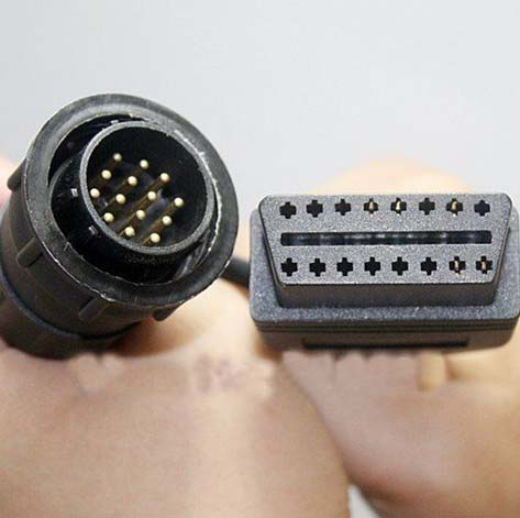
14-Pin Round to 14-Pin DIP Diagnostic Adapter Cable
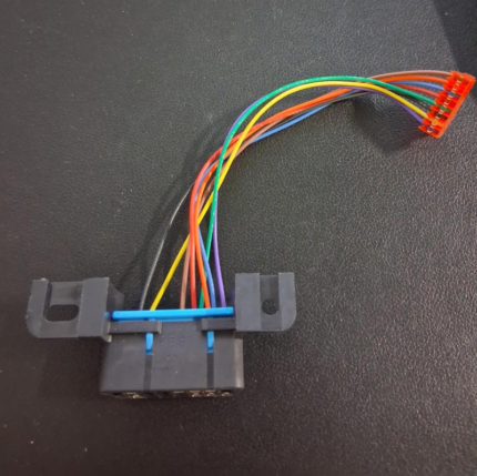
A 14 pin round dip cable bridging a round 14-pin diagnostic plug to a 2×7 DIP socket, so bench tooling built around the DIP format can reach a round port. Straight through, short body, built to the pinout you send.
Overview
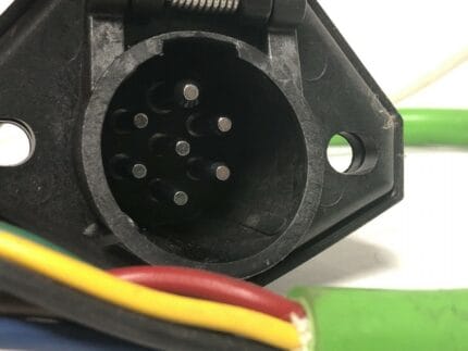
A 14 pin round dip cable is a mechanical bridge between two connector formats that turn up on the same engine family. On one end is a round 14-pin male diagnostic plug, on the other a 14-position 2×7 DIP female socket. Nothing is translated and nothing is regenerated: the adapter exists because the machine presents a round port while the bench tooling was built around the DIP format, and nobody wants to rewire either side. It is short on purpose, because an adapter that hangs off a port under its own weight will work that port loose.
Key Specifications
| Cable Type | Diagnostic Adapter Cable |
|---|---|
| Connector A | 14-Pin Round Male |
| Connector B | 14-Pin 2×7 DIP Female |
| Application | Engine Test Bench / Breakout |
| DIP pitch | 2.54 mm between pins, 7.62 mm between rows |
| Wiring | Straight through as standard; custom mapping per your drawing |
| Function | Passive mechanical and electrical bridge |
| Length | Stated per your drawing |
| Testing | 100% continuity and pinout check before packing |
Two formats, one engine family
The reason this adapter exists at all is that the same engine control unit family can arrive with either connector depending on model year, market, or which harness the machine builder bought that quarter. Knowing what each format is good at tells you which one should be on the port and which one should be on your bench.
| Round 14-pin | 2×7 DIP header | |
|---|---|---|
| Where you meet it | Machine harnesses, cab and engine bay diagnostic ports | Breakout boxes, bench tooling, breadboard and prototype boards |
| Coupling | Threaded or bayonet collar on the shell | Friction only, held by the pin-to-socket contact |
| Sealing | Sealed shells available for exposed ports | None. Indoor, dry, bench use only |
| Strain relief | Built into the shell and the backshell | None unless you design it in |
| Current per contact | Set by the contact size in the series | Signal level; treat it as a signal connector, not a power one |
| Keying | Shell keying and insert rotation | Only the notch in the shroud, which is easy to defeat |
Straight-through, or mapped: decide before you plug in
A 14-pin round diagnostic connector is not one specification. Several machine and engine makers use the same shell with different cavity assignments, so the honest answer to “is it straight through?” is “it is straight through unless you tell us otherwise”. Pick the build that matches the documentation you have.
| Build | How it is wired | When it is the right choice |
|---|---|---|
| 1:1 straight | Round pin 1 to DIP position 1, and so on to 14 | When both sides of your setup use the same numbering and you control the bench end |
| Documented map | Per the pinout you send with the order | When the round side follows a maker convention and you have the service manual in front of you |
| Partially populated | Only the lines you actually use | When the unused cavities add cost and make the bench layout harder to read |
| Flying leads instead of DIP | Round plug to stripped and tinned conductors | When the far end is a terminal strip or a breakout box with screw terminals |
Why keeping it short matters more than it looks
Every centimeter of an adapter is a lever. A 2×7 DIP socket has no strain relief and no locking, so anything hanging off it, or off the round plug at the other end, applies its weight straight to the contacts. Two things follow from that. Keep the adapter short, and support whatever you plug into it. A breakout box sitting on the bench taking the weight of its own leads is fine; the same box dangling from a port is how intermittent faults start, and intermittent faults on a diagnostic port send people chasing faults that are not in the machine.
Construction
- Round 14-pin male plug with the coupling collar for the series you nominate.
- 14-position 2×7 DIP female socket at 2.54 mm pitch.
- Stranded copper conductors, cross section stated on your drawing.
- Overmolded bodies at both ends so strain goes into the mold and not into the solder joints.
- Jacket material per your drawing; oil-resistant compounds for engine bay use.
How to specify your build
- The round side – the connector series and shell you are mating with, and a photo if you have one.
- The mapping – straight through, or the pinout from your service documentation.
- Length, kept as short as the bench layout allows.
- Populated positions – all fourteen, or only the ones you need.
- Quantity, and whether you want them labeled by position.
Typical applications for this 14 pin round dip cable
- Engine test benches where the same ECU family arrives with either connector depending on model year
- Breakout boxes built around DIP inputs, paired with a DT connector pigtail harness at the machine end
- Harness build and repair shops that need a round port to talk to bench tooling, alongside the SAE J1939 OBD2 diagnostic cable
- Industrial engine sets and generator controllers on a stand, next to the black 9-pin J1939 Type 1 adapter
- Prototype and pre-production builds where the port format has not been frozen, with a J1962 female to ECU board harness on the other bench
Workmanship and testing
Build standard for 14-Pin Round builds is IPC/WHMA-A-620 Class 3 under ISO 9001, with terminations from 32 to 12 AWG. continuity and pinout are tested on each 14-Pin unit before it is packed, and seal checking is quoted whenever an ingress rating is on the drawing.
Every production run can ship with RoHS and REACH declarations and the electrical report agreed at quotation; see certifications and material declarations. UL styles and other named approvals are built to drawing: we source to the style you specify and document it, rather than asserting a listing we do not hold. Production runs on the same lines described under our assembly lines in Longgang, where cutting, termination, molding and 100 percent electrical verification sit under one roof. More background: what changes on vehicle harness builds. Tooling is quoted separately, cut in-house rather than brokered out, and owned by you.
Custom builds and ordering
On 14-Pin Round builds, prototype lots run from 1 to 50 pcs and leave in 3 working days; production runs of 500 pcs and up ship 14 working days after sample sign-off. Tooling not already held adds around 10 working days. 14-Pin builds go out under your part number and labeling, and material certificates plus first-article reports are available.
Related bench and diagnostic leads
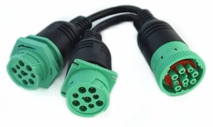
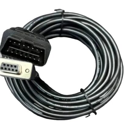
- SAE J1939 OBD2 Diagnostic Cable, Type 2 Green 9-Pin
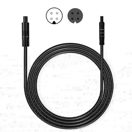
- DT Connector Pigtail Harness, 2 / 3 / 4-Pin Sealed
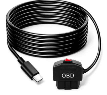
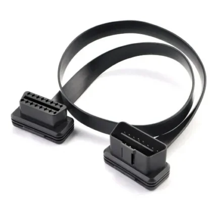
- OBD2 Extension Flat Cable, 16-Pin Male to Female
- 16-Pin J1962F OBD2 Female Connector to ECU Board Harness
- Black 9-Pin J1939 Type 1 Adapter to OBD2 16-Pin Socket
Full range: automotive cable and wire harness.
Frequently Asked Questions
Is this a straight-through adapter?
It is built straight through unless you send us a different mapping. Round 14-pin diagnostic connectors are used by several makers with different assignments, so send the pinout when you can.
Will it convert one protocol to another?
No. It is a passive bridge. It carries whatever the machine puts on the pins, and your tool still has to speak the protocol.
Can you build it with flying leads instead of the DIP socket?
Yes. If your breakout box takes screw terminals or a terminal strip, a stripped and tinned end is usually more useful than a header.
How long should the adapter be?
As short as your bench layout allows. The DIP end has no strain relief, so every extra centimeter is extra leverage on the port.
| Cable Type | Diagnostic Adapter Cable |
|---|---|
| Connector A | 14-Pin Round Male |
| Connector B | 14-Pin 2×7 DIP Female |
| Application | Engine Test Bench / Breakout |
| DIP pitch | 2.54 mm between pins, 7.62 mm between rows |
| Wiring | Straight through as standard; custom mapping per your drawing |
| Function | Passive mechanical and electrical bridge |
| Length | Stated per your drawing |
| Testing | 100% continuity and pinout check before packing |