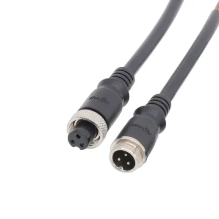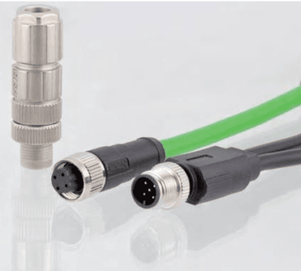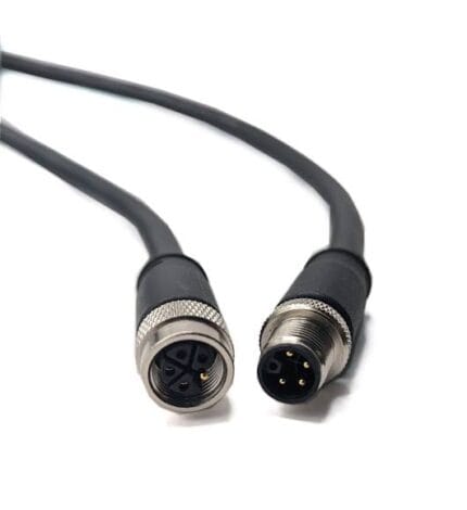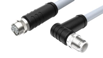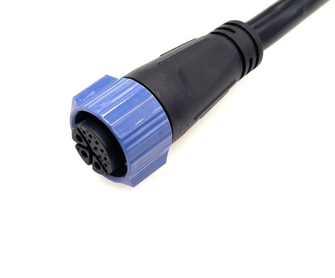
M20 8-Pin Power Signal Cable, 3+5 Hybrid Industrial Cordset
An M20 8-pin power cable that carries signal too: three contacts at power cross-section, five at signal, one sealed shell, one panel cutout. Sealed builds reach IP68 class – a meter for thirty minutes – across a -40 to +105 C service window.
Overview
An M20 8-pin power cable that carries signal too: three contacts at power cross-section, five at signal, one sealed shell, one panel cutout. Sealed builds reach IP68 class – a meter for thirty minutes – across a -40 to +105 C service window.
One Cutout, One Gasket, One Pull
Every hybrid connector is really a promise about the enclosure: one hole instead of two means one gasket, one drain decision, one point to seal on every unit you ship. The 3+5 insert makes that promise practical – three positions sized for current and five for control or data – so an LED driver cabinet, a small servo axis or a chained display column gets mains and its control pair through a single gland. Machine assemblers feel the difference on every unit; service crews feel it on every swap.
What the Ratings Actually Cover
In the 8-pin molded builds most buyers order, contacts carry 60 V at 2 A on 22-24 AWG conductors, which is exactly the budget a 24 V control loop plus a low-voltage LED or drive feed needs. The wider M20 family scales hard in the other direction: low pin-count versions run to 300 V / 15 A on 1.5 mm2 conductors. Cable outer diameter sits between 5.5 and 10 mm, and the compression grommet is selected to your actual cable, because a connector can be IP67 at the face and still leak at the entry if the grommet does not match.
Applications for This M20 8-Pin Power Cable
Intelligent lighting is the anchor application: addressable fixtures and architectural luminaires that want feed and control pair in one connector. LED display cabinets chain power and data panel to panel with the same body. Beyond lighting, machine builders use it for compact drives, valve clusters and irrigation or signage controllers – anywhere two cables would otherwise chase the same gland.
Surviving Real Installations
Housings are glass-filled PA66 rated UL94 V-0, with metal shells available where fixtures get stacked on the connector. Contacts are gold-plated brass laid out as separated power and signal groups, not interleaved, which keeps switching noise out of the quiet lines. Mating life is specified at up to 3,000 cycles on this family, so weekly re-rigging and line changeovers stay well inside the envelope.
Locking Styles: Threaded and Push-Lock
Threaded coupling is the default and the right answer wherever vibration or snag loads exist. Push-lock exists for high-count assembly work – display columns built in a warehouse, fixtures swapped on a bench – where seconds per connection add up and the cable is not going to be yanked in service. Both use the same grommet and seal set, so the ingress rating does not change with the coupling choice.
Ordering and Distribution Builds
Tell us the split – 3+5, 2+3, 2+4 or custom – the current per power position, the signal type, jacket and length. Inline cable-to-cable, cable-to-panel and multi-way distribution bodies that feed several fixtures from one incoming cable are all molded builds we run routinely, and each removes a junction box from the installation.
How Each Assembly Is Verified
Sealed assemblies are leak checked before packing; every unit is continuity and hipot tested and gauge-mated. Insulation resistance is verified at 500 V DC, and the overmold is pull-tested rather than trusted. Test reports and material declarations ship with each batch.
What to Put on the Drawing for a M20 8-Pin Power Cable
A m20 8-pin power cable is released against a drawing, not a catalog description. Put the connector family and keying on each end, the pinout or polarity map, the finished length measured between the mating reference planes, the cable construction you want, and the acceptance tests you expect. If the M20 8-pin power and signal connector has to clear a panel cutout or a bracket, give that envelope too. Anything left open is agreed in writing before tooling or a production slot is committed.
Where a value is not fixed by your drawing we do not invent one. Contact rating, jacket material, sealing class and test limits are recorded as confirm per build, and the released drawing is what the first article is checked against. Send a marked-up sample if a drawing is not available; we confirm the pinout back to you in writing before any M20 8-Pin Power Cable is built.
How to Request a Quote for a M20 8-Pin Power Cable
Send a drawing or BOM, a physical sample, or a written requirement. We log the interface, the application conditions, the environment and the target quantity together, then return an acknowledgement with a list of anything still missing. Pricing is confirm per RFQ and is quoted against the released specification, not against a generic m20 8-pin power cable description.
If the design is not final, say so: we quote the prototype route and hold the production tooling decision until the first article is approved. Drawings are handled under a mutual NDA before they are received. The same document then carries the build from sample through repeat orders, which keeps the M20 8-pin power and signal connector consistent across batches.
Routing and Bend Relief for This M20 8-Pin Assembly
Plan the route before you fix the length. A m20 8-pin power cable that has to turn immediately behind the connector needs clearance for the first bend, and the molded exit is not a hinge. Leave enough slack for service removal, keep the lead away from sharp edges and moving parts, and secure it with clips that grip the jacket rather than crushing it. On cabinet-to-machine power and signal runs, the run usually sees more handling than the specification suggests.
If the assembly passes through a bulkhead or a gland, confirm the opening clears the largest cross-section of the finished connector, coupling included, rather than the cable alone. A M20 8-pin power and signal connector cannot be taken apart after molding, so the route has to accept the finished part. Where space is tight, an angled exit or a shorter body is chosen at quotation, not discovered at installation.
Matching the Jacket and Seal to the Install Site
Tell us what the assembly actually sits in: dust, washdown and cable tray abrasion, cleaning agents, UV exposure, repeated flexing or long static runs. Jacket compound, shield construction and seal geometry follow from that description, and we build to the material you name on the drawing. We do not publish a generic rating for a custom m20 8-pin power cable; the sealing class and the test that proves it are agreed per project and recorded as confirm per build.
If the mating side already has a defined interface, the assembly is built to match it rather than to an assumed standard. A photograph of the install site and the mating part is often enough to settle the exit direction and the clearance. Where a compliance document is needed, the scope is listed at quotation and supplied with the shipment instead of being claimed in advance.
Service, Spares and Repeat Orders
Decide early whether the m20 8-pin power cable is a serviceable joint or a sealed, molded run. A molded assembly is faster to replace on site; a field-terminatable one is kinder to an uncertain route. Spare part numbers, the quantity held and the labeling convention are settled at quotation so the shelf matches the machine rather than the catalog.
Tooling built against your paid development is stored and maintained in our tool room, and we do not sell your geometry to other customers. A repeat order is released from the retained drawing and the retained revision, so the M20 8-pin power and signal connector you fitted earlier is the one you receive again. Any change is confirmed in writing before it enters the build.
Related Cable Ranges
See the rest of the Circular M-Series Cable Assemblies, the outdoor-rated Screw-Lock Molded Cable, and Custom Wire Harnesses for multi-drop distribution. Sealing classes follow the IEC 60529 IP code.
RoHS and REACH declarations are provided per project together with the agreed test reports; the documentation scope is listed under certifications and compliance. If your drawing specifies a UL style, we build to that drawing and supply the UL reference with the shipment instead of substituting an equivalent. Injection parameters for this part are developed against the jacket material using the approach documented under overmolding and injection molding. The wider context is covered under what automation programs ask for. Any tooling we cut for this part stays yours, maintained in our own tool room under your part reference.
| Connector series | M20 waterproof circular |
|---|---|
| Pin count | 8 (3 power + 5 signal), 2+3, 2+4 |
| Insert arrangement | 3 power positions, 5 signal positions |
| Rated voltage | 60 V (8-pin molded builds), Up to 300 V on low pin counts |
| Rated current | 2 A (8-pin signal class), Up to 15 A on 2-3 pin builds |
| Jacket material | PVC, PUR, Rubber |
| Ingress rating | IP67, IP68 (1 m / 30 min class) |
| Cable OD range | 5.5 mm to 10 mm |
| Wire gauge | 22-24 AWG (0.3 mm2) typical, Up to 16 AWG (1.5 mm2) |
| Temperature range | -40 to +105 C |