FPV Drone Video Cable, Right-Angle Mini-USB to 3-Pin Leads
An FPV drone cable picks up video and power at a camera’s mini-USB port and brings them out on two 3-pin leads, so the camera wires to a VTX or flight controller without soldering on the camera board.
Overview
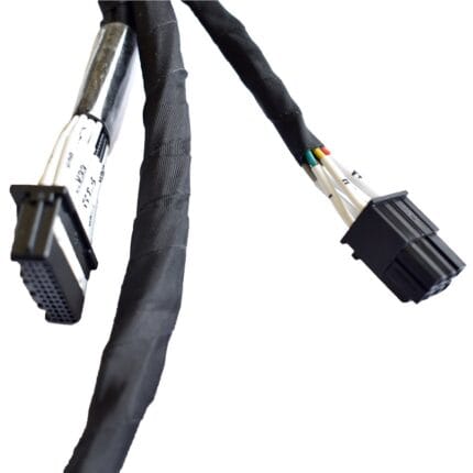
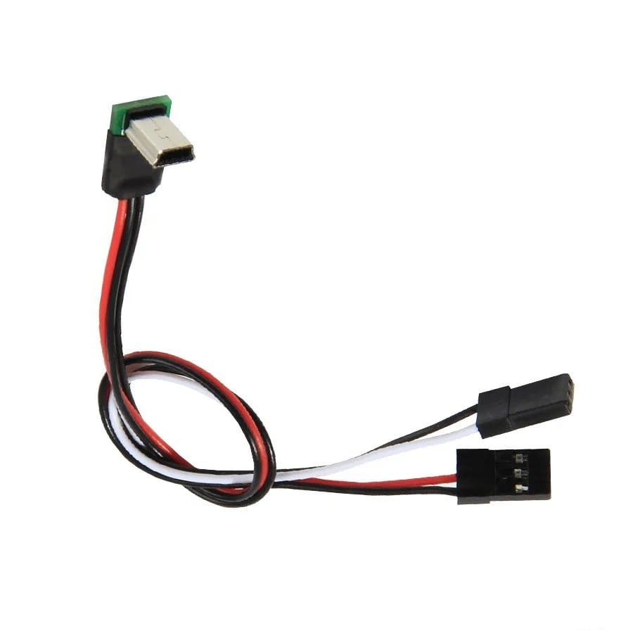
An FPV drone cable has one job: get video and power off the camera cleanly. The photographed assembly starts with a right-angle mini-USB plug, splits into two 3-pin leads, and carries three cores — power, ground and the video signal — built to the pinout on your drawing.
Why cameras hide video and power behind the USB port
Many FPV cameras expose more than data on their USB connector: on several families the video signal is available on one of the USB pins, which lets a single port carry power in and video out. A molded breakout cable turns that into something a builder can use without opening the camera case or soldering to a pad the size of a pinhead.
Right-angle mini-USB plug
The plug in the photo exits at 90° from a molded body. On a frame that matters: a straight plug either fouls the lens mount or levers against the port every time the harness moves. The right-angle exit keeps the plug flat against the camera shell and points the cable along the direction it already needs to run. The overmold at the exit is where most USB cables die; see our overmolding capability for how that transition is built here.
Two 3-pin leads: power, ground and video
The camera end is one plug; the equipment end is two 3-pin servo-style connectors (2.54 mm pitch, one male, one female) so the same assembly lands on either a VTX or a flight controller without adapters. Three cores do the work — power, ground and video/signal — and the mapping of which core lands on which pin follows the drawing, not a guess. Every finished piece is checked for continuity and pinout.
Where the cable runs on the frame
The lead typically runs from the camera at the front of the airframe back to the VTX or FC stack, so length is specified, not standard: too long adds weight and a loop that rattles against the frame, too short tensions the plug. Fine-strand conductors keep the run flexible across the vibrations a lightweight UAV wire harness survives, and the jacket is chosen to match the tape-and-tie method used on the build. For the shielding and drain rules that keep ESC noise out of the video feed, see our drone cable supplier guide to weight, vibration and EMI.
Build options
- Pinout mapped to your camera and VTX documentation
- Length cut to spec, from compact stacked builds to long-range frames
- Connector family on the 3-pin ends per drawing
- Jacket color and marking for build documentation
Quality checks
Continuity and pinout are checked on 100% of pieces — on a video lead the failure mode is not dramatic, it is a channel that shows noise or no image and costs a day of troubleshooting. The pinout check is done against the released drawing, so a swapped core is caught at the bench, not on the airframe. Limits and sampling are agreed in writing before production release.
FPV drone cable vs a stock USB cable
A generic mini-USB cable fails this job twice over: the pinout is not the camera’s video breakout, and the molded strain relief is built for bench use, not for an airframe. This assembly is built to the drawing for both — pinout and strain relief — which is what separates it from the parts bin. Background reading on the connector family: USB hardware.
What to Put on the Drawing for a FPV Drone Cable
A fpv drone cable is released against a drawing, not a catalog description. Put the connector family and keying on each end, the pinout or polarity map, the finished length measured between the mating reference planes, the cable construction you want, and the acceptance tests you expect. If the right-angle camera breakout has to clear a panel cutout or a bracket, give that envelope too. Anything left open is agreed in writing before tooling or a production slot is committed.
Where a value is not fixed by your drawing we do not invent one. Contact rating, jacket material, sealing class and test limits are recorded as confirm per build, and the released drawing is what the first article is checked against. Send a marked-up sample if a drawing is not available; we confirm the pinout back to you in writing before any FPV Drone Cable is built.
How to Request a Quote for a FPV Drone Cable
Send a drawing or BOM, a physical sample, or a written requirement. We log the interface, the application conditions, the environment and the target quantity together, then return an acknowledgement with a list of anything still missing. Pricing is confirm per RFQ and is quoted against the released specification, not against a generic fpv drone cable description.
If the design is not final, say so: we quote the prototype route and hold the production tooling decision until the first article is approved. Drawings are handled under a mutual NDA before they are received. The same document then carries the build from sample through repeat orders, which keeps the right-angle camera breakout consistent across batches.
Fit Check Before You Release the Build
Before release, mate a sample to the real counterpart, not a similar one. Check the keying, the wrench or finger clearance around the coupling, the exit direction relative to the nearest bracket, and the length between the mating reference planes. On FPV airframes and VTX or flight-controller stacks, a right-angle camera breakout that fits the panel but fouls the cover is a common and avoidable revision.
Record the cable diameter you qualified against, especially where a gland or seal is involved. A FPV Drone Cable built at either edge of a seal window does not forgive tolerance scatter the way one in the middle does. Photographs of the fitted sample are kept with the part reference so a later order can be compared against the same configuration.
Electrical Verification Before Shipment
Every fpv drone cable is checked for continuity and pinout against the released drawing before packing, and the mating faces are inspected for full engagement. A swapped core is cheaper to find at the bench than in the field. Where the drawing calls for insulation resistance, dielectric withstand or retention testing, those limits come from your specification and are reported against it; we do not substitute our own numbers.
First article inspection is issued to your format when the order calls for it, with dimensional results and photographs of the critical features. Sealed sections are screened on the agreed test setup. Test scope is fixed in writing before production release so the report that arrives with the shipment describes the build you actually approved.
Prototype, Tooling and Production Quantities
Prototype lots run from 1 to 50 pieces and are built from the same drawing as production, so a sample that works is reproducible. Production starts at 500 pieces per part number. If the right-angle camera breakout needs a new overmold, the tool is designed and cut in our own tool room; more than 3,000 tooling sets have been built since 2012, and the tool cut for your program belongs to your program.
The first article is submitted before the production run, and changes to connector, cable, pinout or mold geometry are confirmed in writing before they are implemented. Keeping prototypes and production on one document is what stops a revision from quietly changing a FPV Drone Cable between the sample and the order.
How to order
Send the drawing or a marked-up sample: pinout, gauge, length, connector family on the 3-pin ends. The assembly is quoted and built through the standard custom wire harness flow, with prototypes and production released from the same document.
RoHS and REACH declarations are provided per project together with the agreed test reports; the documentation scope is listed under certifications and compliance. If your drawing specifies a UL style, we build to that drawing and supply the UL reference with the shipment instead of substituting an equivalent. Right-angle exits are molded rather than bent, following the exit forms and tooling described under right-angle overmold tooling options. More background: prototypes and first article inspection. Any tooling we cut for this part stays yours, maintained in our own tool room under your part reference.
| Build Type | Build to drawing or build to sample |
|---|---|
| Application | FPV camera video and power breakout to VTX or flight controller |
| Connector A | Mini-USB male, right-angle, molded |
| Connector B | Two 3-pin servo-style connectors, 2.54 mm pitch, male and female |
| Conductors | 3 cores: power, ground, video/signal |
| Wire Gauge | Fine-strand, sized per the drawing |
| Length | Cut to spec per order |
| Testing | 100% continuity and pinout check |
Related products