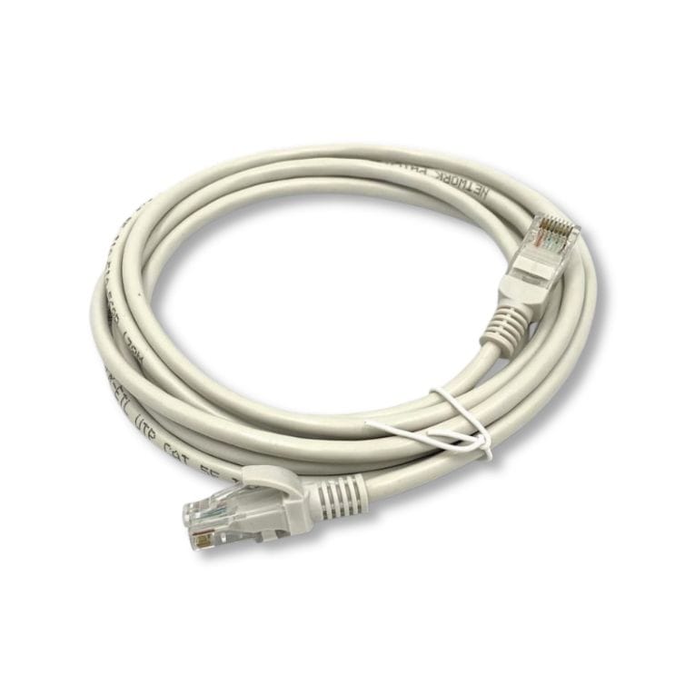
Cat5e UTP Patch Cord
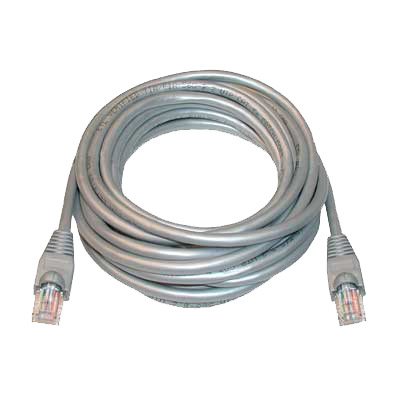
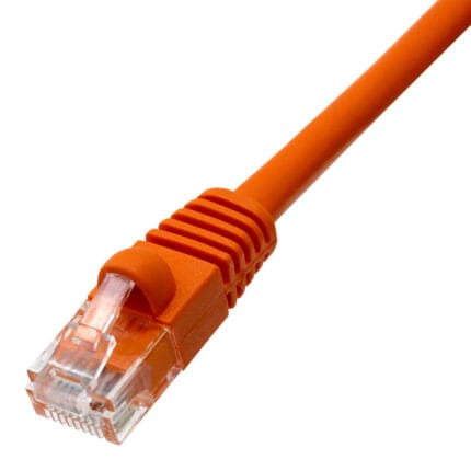
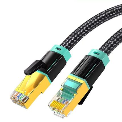
A cat5e utp cord is the everyday link between a switch, a patch panel, a wall outlet and the device at the end of the run. Four 24 AWG solid pairs, RJ45 to RJ45, snagless boot.
Overview
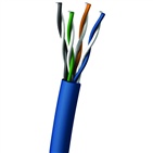
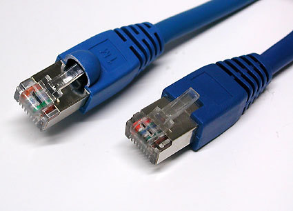
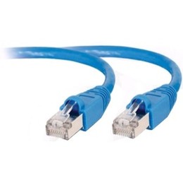
A cat5e utp cord is the everyday link between a switch, a patch panel, a wall outlet and the device at the end of the run. It is four unshielded twisted pairs of 24 AWG solid bare copper, insulated with HDPE and jacketed in hard grade PVC, terminated with RJ45 plugs at both ends. The result is a stable 100 ohm channel that carries Gigabit Ethernet, PoE and legacy 10/100 traffic without the cost and the handling difficulty of shielding that most office runs never need. Deciding when that is the right answer, and when it is not, is the whole of the selection job.
Key Specifications
| Cable Category | Cat5e (Category 5e) |
|---|---|
| Shielding | UTP (Unshielded Twisted Pair) |
| Conductor | 24 AWG solid bare copper (0.5 mm) |
| Insulation | HDPE, 0.96 mm nominal diameter |
| Jacket | PVC hard grade, 5.2 mm nominal diameter |
| Connector | RJ45 male to RJ45 male |
| Bandwidth | 350 MHz |
| Impedance | 100 ohm +/-15% |
| DC Resistance | 9.38 ohm/100 m max |
| Compliance | ANSI/TIA/EIA-568-C.2, ISO/IEC 11801, IEC 61156-6 |
| Flame Rating | IEC 60332-1-2, NFPA-90A |
| Operating Temperature | -10 deg C to +75 deg C |
Is unshielded still the right default?
For the majority of office, campus and retail drops, yes. An unshielded Category 5e channel is cheaper, lighter, easier to terminate and easier to route, and in a benign electromagnetic environment the shield would do nothing measurable. Shielding earns its place when the channel is genuinely exposed, and it brings obligations with it if the screen is not continuous and grounded, it can make things worse rather than better.
| Route | Unshielded is correct | Step up to a screened cord |
|---|---|---|
| Office floor, inside a ceiling or a tray with data only | Yes | No advantage; save the cost and the termination time |
| Beside motor drives, transformers or large switchgear | No | Yes – and the panel and equipment cords must be screened too |
| Parallel to power cable for a long distance | Depends on separation | Yes if separation cannot be maintained |
| Industrial cell with welders or inverters | No | Yes, plus a proper ground path |
| Near radio transmitters or broadcast equipment | No | Yes, and check the screen termination |
| Normal patch panel to switch, inside one rack | Yes | No |
If the route is exposed and you decide to screen it, screen the whole channel: a Category 5e foiled cord covers the moderate case, and the screening has to continue through the panel and the equipment leads to be worth anything.
What 24 AWG means when you pull and when you power
Two separate limits come from conductor size. The mechanical one is pulling: a 24 AWG solid conductor is thin, and a hard pull stretches it, which changes the impedance along the length and shows up as a marginal return loss rather than an open circuit. The electrical one is resistance: the DC resistance figure in the specification is what sets the voltage delivered at the far end of a PoE run, and it is why long PoE drops need more copper rather than a bigger supply.
- Pull on the cable, not on the plug, and support the run along the route.
- For long PoE runs, check the delivered voltage at the device, not at the switch.
- Solid conductors belong in fixed runs. Where a cord is re-patched daily, tell us and we will quote a stranded build instead.
Solid or stranded, T568A or T568B
Solid conductors are for permanent links that are terminated once and left alone; stranded conductors tolerate repeated flexing and belong in cords that get moved. The termination standard is the other choice, and it matters less than people think, provided you are consistent. Mixing T568A at one end and T568B at the other produces a crossover cord, which is occasionally exactly what you want and usually an accident.
- Pick one standard for the site and label it on the drawing.
- Use a crossover cord deliberately, and mark it, rather than discovering one at commissioning.
- Test every cord before it goes into a panel; a cord with one pair reversed is the most common cause of a link that negotiates at 100 Mbps instead of a Gigabit.
Where a cat5e utp cord gets used
- Horizontal patching between wall outlet and desktop in offices and campuses
- Switch to patch panel links in telecom rooms and wiring closets
- VoIP phones, printers, access points and IP cameras over PoE
- Test bench and lab connections where short patch leads are re-patched daily
- Retail and hospitality installs where Gigabit is all the traffic needs
- Dense panels, where our Cat5e UTP Short-Body Patch Cord saves depth
How to specify the build
- Length of each cord; mixed lengths are normal.
- Color, and whether colors code for a service, a VLAN or a department.
- Boot style – snagless as standard, or short-body for dense panels.
- Pinout – T568A or T568B, and whether you need any crossover cords.
- Conductor – as stated on your drawing; tell us if the application needs stranded.
- Quantity, and whether this is a prototype or a production order.
Workmanship and testing
Cat5e UTP builds are assembled and inspected to IPC/WHMA-A-620 Class 3 criteria, with ISO 9001 as the quality system over 32 to 12 AWG work. continuity and pinout are verified on each Cat5e assembly before packing, and seal checking is quoted whenever an ingress rating is on the drawing.
RoHS and REACH declarations are provided per project together with the agreed test reports; the documentation scope is listed under certifications and compliance. If your drawing specifies a UL style, we build to that drawing and supply the UL reference with the shipment instead of substituting an equivalent. Overmold tooling for this part is designed and cut in our own tool room under the overmold tooling we build in-house, so the tool belongs to your program and a revision is a machining job rather than a new negotiation. The wider context is covered under our industrial automation work.
Custom builds and ordering
Cat5e UTP prototype builds start from 1 to 50 pcs and are out in 3 working days; production is quoted from 500 pcs at 14 working days after sample approval. Your part number and labeling go on OEM and ODM Cat5e shipments, and material certificates plus first-article reports are available. We hold 100 sets of mold tooling in house, so a standard body needs no tooling time and a new one adds about 10 working days.
What is listed here for Cat5e UTP builds is the industry-standard definition, not a measurement we took on a finished part. What your assembly is built and verified to is what your drawing states, confirmed against the supplier datasheet before a quote goes out.
Related Cat5e and Ethernet patch cords
- Cat5e UTP Snagless Patch Cord, 350 MHz
- Cat5e UTP Crossover Patch Cord, T568A to T568B
- Flat Slim Cat6 / Cat5e UTP Patch Cord
- Cat5e UTP LSZH Patch Cord, 350 MHz
- Cat5e UTP etherCON Patch Cord
- RJ14C 6-Pin Modular Patch Cord
Full ranges: Ethernet patch cords and signal and data cables.
Frequently Asked Questions
Will Cat5e run Gigabit?
Yes. Gigabit Ethernet was designed to run over Category 5e, and it is the standard choice for that application. Cat6 buys margin, not a different speed at the desktop.
Why does my link only negotiate 100 Mbps?
Usually a single pair that is open or reversed. Test the cord before it goes into the panel; it is far cheaper than diagnosing it after the ceiling is closed.
Can I use these outdoors?
Not this build. Outdoor and direct-burial runs need a jacket and often a gel-filled construction made for it; ask for the outdoor version rather than using an indoor cord.
Should I pay for shielding anyway?
Only if the route is exposed. In a benign environment a screen adds cost, stiffness and a grounding obligation, and delivers no measurable improvement.
| Cable Category | Cat5e (Category 5e) |
|---|---|
| Shielding | UTP (Unshielded Twisted Pair) |
| Conductor | 24 AWG solid bare copper (0.5 mm) |
| Insulation | HDPE, 0.96 mm nominal diameter |
| Jacket | PVC hard grade, 5.2 mm nominal diameter |
| Connector | RJ45 male to RJ45 male |
| Bandwidth | 350 MHz |
| Impedance | 100 ohm +/-15% |
| DC Resistance | 9.38 ohm/100 m max |
| Compliance | ANSI/TIA/EIA-568-C.2, ISO/IEC 11801, IEC 61156-6 |
| Flame Rating | IEC 60332-1-2, NFPA-90A |
| Operating Temperature | -10 deg C to +75 deg C |