
Overmolding & injection
In-House Overmolding & Injection Molding for Cable Assemblies
Strain relief, sealed boots, integrated branding and insert retention formed in one shot — in PVC, TPE, TPU, PP, PA and PUR.
Three problems solved in one shot, or none of them.
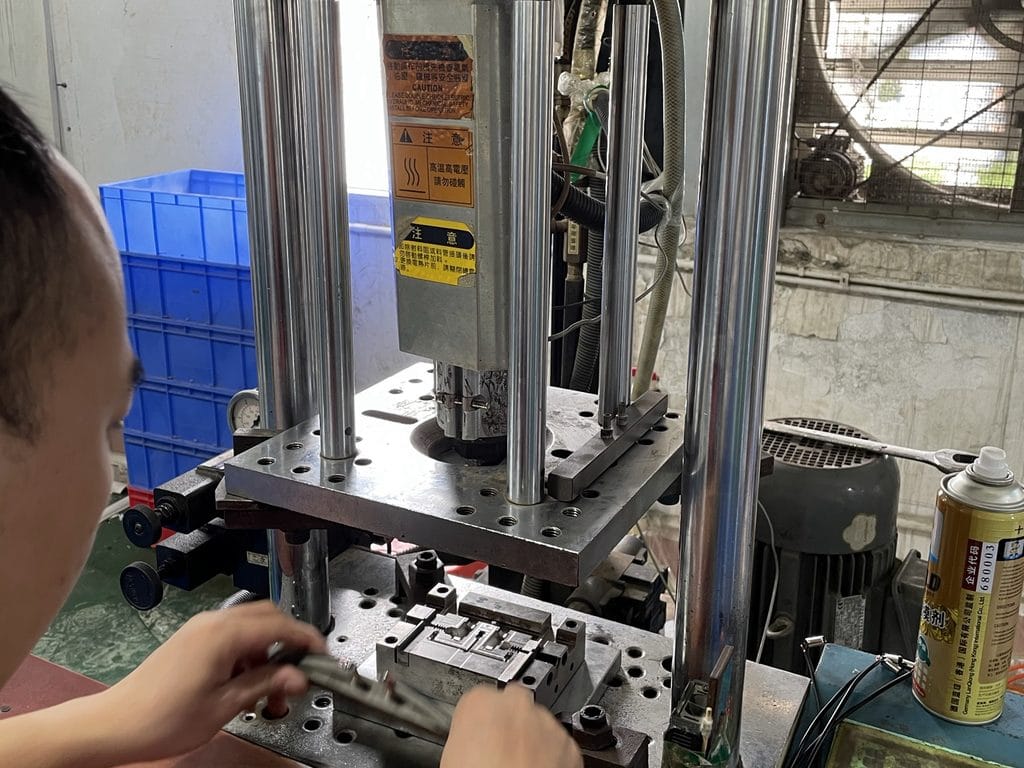
HKWIRE is a custom cable assembly manufacturer and OEM/ODM supplier in Longgang, Shenzhen — and overmolding is done in-house. The tool room, the molding floor and the assembly lines share one facility, which is what lets us hold exit geometry, sealing and cycle time to the numbers we quote.
Overmolding solves three problems at once: it locks the connector to the cable, it controls where the cable bends, and it is the only realistic way to make an interface survive a wet, oily or high-vibration environment. Done badly it does none of these, and adds a failure point where there was none.
Material selection.
| Material | Where it fits | Trade-off |
|---|---|---|
| PVC | General indoor, cost-sensitive, wide color range | Stiffens in cold; limited flex life |
| TPE | Handheld devices, flexible strain relief, soft-touch | Lower chemical resistance than TPU |
| TPU | Drag chain, abrasion, oil exposure, robotics | Higher material and processing cost |
| PP / PA | Structural bodies, higher temperature, chemical resistance | Bonding to cable jacket needs specific design |
| PUR | Abrasion and hydrolysis resistance, outdoor and marine | Process window is narrower than PVC |
| Silicone | High-temperature and medical-adjacent builds | Requires dedicated process control |
Bonding is a design decision, not a hope. We confirm jacket material and surface condition before tooling, because an overmold that looks fine at T1 can delaminate at month six if the two materials were never meant to bond.
An overmolding line you can audit
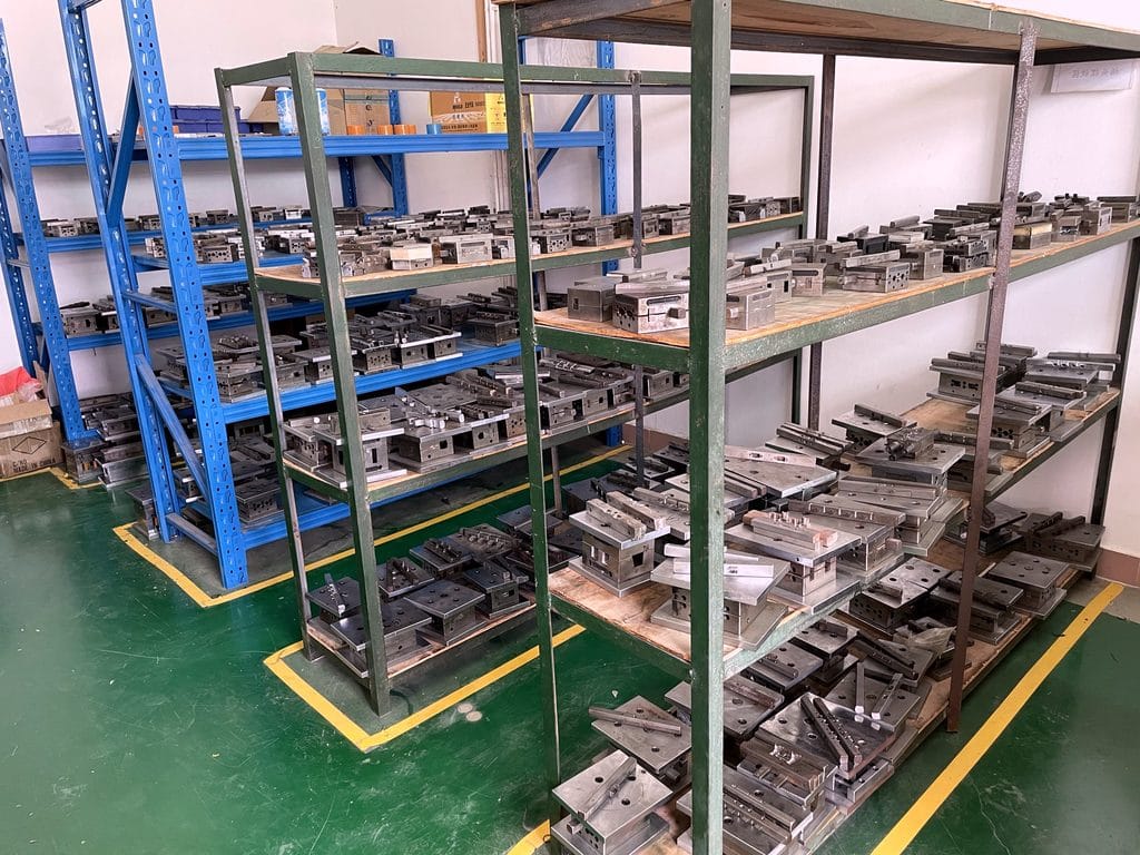
We are a manufacturer, not a sourcing desk. Overmold tooling is designed and cut in our own tool room — the shelves below hold molds built for programs in production today — so a mold adjustment is a machining job on our floor, not a phone call to another company. Molding, assembly and electrical testing and validation share one roof, which is how prototype samples leave in as fast as 3 working days and production runs ship 14 working days after approval.
Factory audits are welcome — in person or by live video walk-through of the molding area, assembly lines and inspection benches, arranged in advance. We build and inspect to IPC/WHMA-A-620 Class 3 workmanship criteria under an ISO 9001 certified quality management system, and every overmolded harness passes 100% continuity and pinout testing before it is packed.
What we control, and what goes wrong when nobody does.
- Insert movement
- Connector shifting during injection causes pin misalignment. Controlled by holder design and injection sequence.
- Flash at the parting line
- Controlled by tool fit, clamp tonnage and shot parameters; checked at first-piece and in process.
- Short shots at the cable exit
- Usually a gating or venting issue. Resolved at mold concept stage rather than by raising temperature.
- Delamination from the jacket
- A material compatibility and surface-preparation issue — confirmed before tooling, not after.
- Sink marks on thick sections
- Controlled by wall-thickness uniformity in the mold concept, not by packing pressure alone.
- Stress cracking at the strain relief
- Geometry and radius design, validated by bend and pull checks before release.
Options available.
- Exit geometry — straight, right-angle or custom exit angle
- Color — Pantone or sample match
- Identification — molded-in logo or part number
- Strain control — integrated strain relief and bend limiter
- Sealing — sealed boots and gasket paths to IP65 / IP67 / IP68 / IP69K design targets
- Low-pressure molding — for delicate inserts and thin-wall connectors
- Integration — overmold-to-panel or overmold-to-bracket geometry
Typical applications run from automation and robotics to medical devices and automotive and EV builds — anywhere a molded boot has to survive flex, fluid or washdown. For reference builds, browse our custom wire harnesses and M8 and M12 circular cables.
Tell us the connector, the jacket and the environment.
Tell us four things and we can usually quote within a working day:
- Connector and jacket material — or a drawing or a physical sample
- Exit geometry, sealing target (IP65–IP69K) and color
- Quantity — prototype count and projected annual volume
- Target delivery date and ship-to country
We come back with the engineering questions that affect the mold, the material we recommend and a lead time we can hold — before you commit.
Overmolding FAQ
What is your MOQ for overmolded cable assemblies?
Production orders start at 500 pcs; prototype builds from 1 to 50 pcs.
How fast can you deliver?
Samples in 3 working days. Production runs ship 14 working days after approval; allow about 10 working days more when a new mold has to be cut.
Can you overmold to our drawing?
Yes — build-to-print is our default as an OEM and ODM manufacturer and supplier. Send a PDF or STEP file with the connector and exit geometry, and we confirm moldability before cutting; see build-to-print cable assemblies.
Do you make the molds yourselves?
Yes. Overmold and injection molds are designed and cut in our own tool room — 3,000+ tooling sets built since 2012, with 100+ active molds maintained on site — with a DFM review of jacket bonding and shrinkage before steel is cut.
Can we visit or audit the factory?
Yes. On-site audits or a live video walk-through of the molding area and assembly floor can be arranged in advance.